-
CNC High-Speed Drilling Machine
-
CNC Drilling Machine
-
CNC Hydraulic Punching Marking Machine For Plate
-
Beam Band Saw Machine
-
Beam Drilling Line
-
CNC Punching/Drilling Marking Shearing Line For Angle
-
CNC Flat Bar/Channel Process Line
-
Straightening Machine
-
CNC Laser Machine
-
Screen Plate Wholesale
-
Marking Machine
-
Notching Machine
-
CNC Woodworking Machine
-
Other CNC Machine
-
Testing Machine
-
Accessory
-
 Mr. BegallTo:Jinan FAST CNC Machinery PLC Dear Sir, With the letter we would like to thank for your cooperation in the successful installation, testing and commissioning of High Speed CNC Drill Of First in its kind Ethiopia , that would enable us do many works especially sugar product tube plate holes of various deameters and thickness. ... With Regards
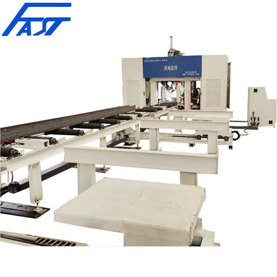
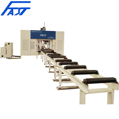
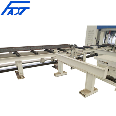
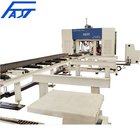
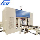
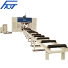
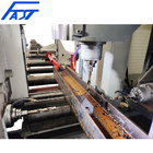
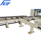
Jinan FAST High-Speed CNC H Beams Drilling Machine Used For Steel Constructure fabrication

Contact me for free samples and coupons.
Whatsapp:0086 18588475571
Wechat: 0086 18588475571
Skype: sales10@aixton.com
If you have any concern, we provide 24-hour online help.
x| H-beam Max.height × Max.width (Flangewidth) | 650×300mm | H-beam Min.height × Min.width (Flangewidth) | 150×100mm |
|---|---|---|---|
| Automatic Feed Conveyor Length | 12000mm | Max.workpiece Web Thickness | ≤25mm |
| Maximum Workpiece Weight | 2000kg | Number Of Drilling Spindles | 3 |
| Drilling Diameter Range | φ5-30 | Drilling Spindle Power | 11Kw |
| Spindle Taper Hole | BT40 (Pneumatic Loosening Tool) | Adjacent Hole Group Hole Spacing Error | ±0.2 |
| Name | Specification | |
|---|---|---|
| Color | Black & White | |
| Controlling System Language | English (Option: Russia) |
Jinan FAST High-Speed CNC H Beams Drilling Machine Used For Steel Constructure
![]()
1. APPLICATION
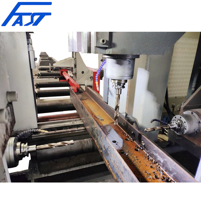
This machine is mainly used for drilling H-beam, channel steel and box beam, and is widely used in steel fabrication buildings, bridges, three-dimensional garages and other industries. The 7-axis CNC section steel 3D drilling machine adopts seven servo motors to realize drilling positioning in two vertical directions, one horizontal direction and one longitudinal direction and servo feeding of three spindles. There are 3 drilling surfaces, each with 1 drilling spindle, and 1 drilling spindle on each surface is driven by a frequency conversion motor. The drilling spindle is a servo feeding drilling spindle. When the hole diameter of the workpiece is 1, the holes on the three sides of the workpiece can be processed after passing through the machine at one time, with high efficiency and high hole position accuracy.
It is an indispensable machine to ensure quality in the steel fabrication manufacturing industry.
2.TECHNICAL DATA
| Name | Unit | Specifications | ||
| H-beam: Max. height × Max. width (Flange width) | mm | 650×300 | ||
| H-beam: Min. height × Min. width (Flange width) | mm | 150×100 | ||
| Automatic feed conveyor length | mm | 12000 | ||
| Max. workpiece web thickness | mm | ≤25 | ||
| Maximum workpiece weight | kg | 2000 | ||
| Number of drilling spindles | 个 | 3 | ||
| Drilling Diameter Range | mm | φ5-30 | ||
| Upper unit spindle technical parameters | Number of upper spindles | KW | 11 | |
| Spindle rated torque | Nm | 140 | ||
| Spindle speed range | r/min | 0~3000 | ||
| Axial feed speed | mm/min | 0~4000 | ||
| Spindle feed stroke | mm | 400 | ||
| Spindle centerline lateral movement range | mm | 30~600 | ||
| Left unit spindle technical parameters (reference side) | Drilling spindle power | KW | 11KW | |
| Spindle rated torque | Nm | 140 | ||
| Spindle speed range | r/min | 0~3000 | ||
| Axial feed speed | mm/min | 0~4000 | ||
| Spindle feed stroke | mm | 200 | ||
| The moving range of the spindle center line up and down | mm | 20~270 | ||
| Right unit spindle technical parameters | Drilling spindle power | KW | 11KW | |
| Spindle rated torque | Nm | 140 | ||
| Spindle speed range | r/min | 0~3000 | ||
| Axial feed speed | mm/min | 0~4000 | ||
| Spindle feed stroke | mm | 500 | ||
| The moving range of the spindle center line up and down | mm | 20~270 | ||
| Spindle taper hole |
BT40 (Pneumatic loosening knife) |
|||
| Hole spacing error in hole group | mm | ≤±0.2 | ||
| Adjacent hole group hole spacing error | mm | ±0.2 | ||
| Bit cooling method | spray cooling, external cooling | |||
| Up and down (vertical) stroke of gripping arm | mm | 100(50-150) | ||
| Left and right (lateral) stroke of gripper arm | mm | 150(50-300) | ||
| Gripper arm movement (forward direction) stroke | mm | 12000 | ||
| Rack and pinion drive servo motor power | KW | 5 | ||
|
Outline dimensions of feeding channel (L× W × H) |
mm | 14000×900×1630 | ||
| Feed channel length | mm | 8000 | ||
| total power | KW | About 50 | ||
| Dimensions of the production line L×W×H | mm | Abou 24000×3500×3120 | ||
| Automatic conversion of CAD drawings into machining programs | ||||
3. DETAIL PICTURES
![]()
![]()
![]()
![]()
![]()
![]()
![]()
![]()
![]()
![]()
![]()
![]()
COMPANY PROFILE
![]()
WORKSHOP
![]()
CUSTOMER VISIT
![]()
FAQ
![]()
CERTIFICATE
![]()
PACKING AND SHIPPING
![]()


